|
General
HVAC part in this item will include ventilation system and air condition system
Technology descriptions
(1) Ventilation system
A great amount of heat will be released in the main power building where the diesel generator units in operation. The heat should be exhausted to the atmosphere to ensure safety operation of units. Blower box with filter is used to supply the air and power roof ventilators are used to exhaust the air. The blower box is installed at the bottom of the building; it will draft the outdoor air into the building to cool the diesel generator units. The hot air will be removed through the roof ventilators at the top of the building.
Natural inlet and mechanical exhaust ventilation by axial fan will be provided for the auxiliary boiler house to exhaust the excess heat, humidity and harmful gas.
Natural inlet and mechanical exhaust ventilation by axial fan will be provided for the distribution rooms and cable interlayer located in the main power building, demineralized water station, auxiliary boiler house, composite water pump house, and other buildings in order to exhaust the excess heat, excess humidity and harmful gas. The mechanical ventilation system in distribution room is also used as emergency ventilation system. The ventilation rate in distribution room is not less than 10 times per hour, while the ventilation rate in cable interlayer is not less than 6 times per hour.
Natural inlet and mechanical exhaust ventilation will be provided for the ammonium room and water analysis room. The axial fan used in the ammonium room will be anti-explosive and the air changes will not be less than 15 times per hour. The air changes in the water analysis room will not be less than 10 times per hour. Mechanical exhaust ventilation will be provided or the laboratory hood in the water analysis room.
The air changes in the composite water pump house will not be less than 6 times per hour.
(2) Air conditioning system
In this project, split air-conditioning will be adopted to ensure proper working environment both for men and machines and to protect the electronic devices and data-processing equipments from high temperature.
Air-cooled packaged air conditioners will be provided for control room, DC room, switchgear room to meet the technical requirements and ensure proper working environment for the operator.
Air-cooled split air conditioners shall be provided for local control room, laboratories, and offices and so on.
The indoor temperature will be controlled between 25┬░C and 30┬░C in summer and between 15┬░C and 20┬░C in winter.
The exhaust heat recovery boiler is the water tube type exhaust boiler with the forced circulation type. Every diesel is equipped with one boiler (all 6 sets). The six (6) Gen-sets as one set will be equipped with 1 steam pocket, 6 boiler water pump and 6 water circulating pump. One boiler duty is 2000kg/h (according to 100% diesel working situation), the superheated steam pressure is 0.7MPa (g), the temperature is 173┬░C. Three boiler share one deaerator and one superheater steam points of the cylinder. The boiler is composed of welding fin-root with expansion of heating, which is lineposition in order to the air current circulate. The waste gas in the boiler flows downward, first to the superheater, then to the evaporimeter and finally to the economizer. The whole boiler system is comprised of the exhaust gas boiler, the horizontal drum, the deaerator, the feed pump, the hot water circulating pump, the electrical control panel, the chemical dosing device and the system accessories. When the diesel is working, the exhaust-heat boiler absorbs the exhaust gas produced by the diesel to produce the superheated steam for the steam turbineŌĆÖs power generation and saturated vapor for heating the lubricating oil so as to saving fuel and improving the unit efficiency of generator sets for the purpose of economy and energy conservation. When the steam turbine does not work, steam is directly led from the superheater steam points of the cylinder to heat the deaeartor and lubricating oil.
Scope of supply exhaust hot recover system(Subject to final design of the institute)’╝ÜIncluding the entire boiler island, that all the equipment, support, escalators, pumps, piping, valves, cables and installation materials in the boiler system.
7.1 Exhaust hot recover boiler unit
Each boiler would be supplied with the following:
- Superheater section
- Evaporator section and economizer section
- Steel frame
- Independent integrated smoke box
- Inlet gas canopy complete with access door.
- Exhaust gas hopper complete with access door, large bore drain port and supporting steelwork
- Soot blowing system
- ŌĆśT’┐Į?gas bypass, with 2 damper blades, inter connected and supplied with a pneumatically operated actuator complete with positioner to enable the dampers to modulate to control the drum steam pressure and in emergency close the boiler gas flow when other cases require boiler shutdown.
- Guillotine inlet/outlet dampers.
- Instrument & control system
Each drum will be designed for the steam capacity from 6 exhaust gas boiler. Each drum is connected to the superheater, evaporator section and economiser section and supplied loose for transportation.
7.3 Boiler control panels
We supply 6 boiler control panels which would control 1 steam drums and 6 boilers and would be floor mounted .The protection class is IP44.The panel Control the entire boiler system and signal contacts by PLC.The control floor mounted incorporating operational logic and control loops for steam drum level.Boiler also contains the control of soot blower box.
Control functions for deaerator
- Water level control ’┐Į?via treated make up water control valve and overflow valve.
- Temperature control ’┐Į?via steam control valve.
- Remote monitoring/alarm functions ’┐Į?via communication cable
- Water level indication
- Water level alarm high/low
- Steam pressure in Deaerator
Control functions for drumand boiler
- Water level control ’┐Į?via feed control valves for each steam drum
- Steam pressure control ’┐Į?via boiler bypass and damper
- Remote monitoring/alarm functions for one deaerator ’┐Į?via communication cable..
- Water level indication
- Water level alarm high/low
-Steam pressure
7.5 Sootblower cleaning equipment
Each boiler would be supplied with 6 electric motor driven multi nozzle rotating element sootblowers, each complete with:
• Motor
• Multi-jet element of carbon steel material
• Element supported by internal bearings ’┐Į?supplied loose
• Poppet valve of Series 40 bar carbon steel
• Wallbox, positive pressure
• Single limit switch
•Air relief/scavenging valve
• Non-asbestos packings and gaskets.
• Thermal cover assembly.
Sootblower control system
- LCP local contactor panel with PB and Lamp on LCP door PLC in above LVP controlling
- Main valves air operated
’┐Į?Drain valves air operated
’┐Į?Sootblowers
’┐Į?Pressure switches
7.6 Steam header for boilers superheaters
We would supply 1’┐Į?Superheater header with 2 ’┐Į?inlet valves, startup valve and pressure indicator. Also steam trap, common temperature and pressure transmitters and pressure indicator local to header plus outlet line with isolation valve .
We supply one set of Blowdown Equipment,the capacity of which to meet the steam turbine outage oxygen and steam heating needs of heavy oil
8.1.1 The data provided by the sealer should be the national legal system of units, ie International System of Units, language be Chinese, the foreign drawings and files of import parts be provided foreign original documents. The sealer will provide the whole information and drawing according to units technical specifications, technical requirements, scope of supply and guaranteed conditions.
8.1.2 The drawings offered by the sealer should be clear and micro-copied drawings are forbidden to be offered. The organization structure of data is to be clear and strict in logic. The content of data must be correct, accurate, clear and comprehensive, meeting the project.
8.1.3 The sealer should provide the data related with the equipment design in time.
8.1.4 If to be found, the sealer will provide the files and data free of charge to other data not lined in the contract but project to be needed. When the equipment make an improvement, the sealer will provide the new technical data free of charge in time.
8.2 Basic requirements of information presentation
8.2.1 Technical files of coordination with project design data and drawings
The sealer will provide the data and drawings satisfied for the project design, project installation and operation maintenance.
As shown below:
|
No. |
Designation |
Qty. |
Remarks |
|
1 |
Outside diagram of generating set |
1 |
AUTOCAD E-document |
|
2 |
Erection diagram of generating set |
1 |
AUTOCAD E-document |
|
3 |
Overhaul dimension diagram of main components |
1 |
AUTOCAD E-document |
|
4 |
System diagram of generator |
1 |
AUTOCAD E-document |
|
5 |
Sensor list for generating set |
1 |
|
|
6 |
Heat balance table of engine |
1 |
|
|
7 |
Torsional vibration calculation for generating set |
1 |
|
|
8 |
Outside diagram of generator |
1 |
AUTOCAD E-document |
|
9 |
Shafting dimensions of generator |
1 |
|
|
10 |
Schematic diagram of electrical system |
1 |
|
|
11 |
Assembly and connection dimension diagram and erection diagram of external auxiliary equipments
|
1 |
AUTOCAD E-document |
8.2.2 The technical files as data and diagram delivered with equipment
The sealer shall provide the needed data and diagram satisfied for the project installation, pre-commissioning, performance acceptance and operation maintenance in time (rather than the following files).
|
No. |
Designation |
Qty. |
Submission time |
Remarks |
|
1 |
Drawings of unit profile, external auxiliary equipment and connection dimension, installation drawing |
6 sets |
Delivered with the equipment |
|
|
2 |
Principle diagram of system electricity, switch cabinet |
|
3 |
Diagram of units control system |
|
4 |
Diagram of external auxiliary equipment control system |
|
5 |
Switch cabinet, outlet cabinet installation and connecting diagram |
|
6 |
Installation operating instructions |
|
7 |
Operating instructions |
|
8 |
Maintenance instructions |
|
9 |
Atlas of spare parts |
|
10 |
List of spare parts about operation maintenance and loss |
|
11 |
List of equipment packing |
|
12 |
certification by manufacturer |
9.1 Delivery requirements
The buyer is responsible for delivering the equipment and insurance for transportation expenses.
9.2 Package requirements
The sealer is in charge of equipment package, the package costs included in the total amount. The package and delivery be in accordance with the specifications of GB191-73 pictorial markings for handling of packages.
9.3 Place of delivery
Place of delivery in the sealerŌĆÖs factory, the buyer should recognize the dispatch goods with the sealer helping to provide truck loading.
9.4 If the damage and loss happen to the equipment in transportation, the sealer will negotiate with the carrier and claim for compensation.
10.1 Warranty period
Warranty period under scope of supply is one year. In the warranty period, the second party is in charge of free, for the problem of building in quality produced by the defects in equipment manufacture. After the warranty period, the sealer provides the technical consultation free of charge and the spare parts at the best price, also responsible for the life-long maintenance.
10.2 Guarantee of field service
In the warranty period, the sealer could provide more timely and comprehensive service guarantee. The spot service engineers sent by JICH are for the after-sales guaranteed work and train the spot operation workers, with food and accommodation provided by the buyer.
10.3 Technical training----to provide the training service free of charge
The sealer can provide the training of five days for ten persons, with food and accommodation provided by the buyer.
10.4 Installation of on-site guidance and commissioning
The sealer is responsible for the installation of equipment and commissioning; while the buyer is for solve the just requirements of the spot service engineers in order to ensure all tasks are carried.
10.5 Commitment
10.5.1 The aptitudes for spot service engineers of the sealer as follows:
a. Compliance with law, each rules and regulations on site.
b. In place on time with strong enterprise and responsibility.
c. Knowing about the equipment design in contract, familiar with the structure, having the spot working experience of the same or similar unit, able to do the spot guidance work correctly.
d. Healthy for the condition of field work.
10.5.2 The responsibilities of the spot service workers
a. The tasks mainly include the processing about problems of equipment quality, guidance for installation and commissioning, participation in trial running and acceptance functional test.
b. Before installation and commissioning, the technical workers should speak clearly to the buyer, explained and demonstrate the procedures and methods to be going.
c. The service workers have the right to dealing with all the problems of technology and business, ie, the service workers have to resolve the problems within the time allowed by the buyer, if the quality problems happen. If the sealer entrusts the buyer resolve the problem, the spot service workers of sealer must have the power of attorney and afford the related economic responsibility.
d. Pre-negotiation to the buyer about the normal come& go and change of the spot service workers.
10.5.3 The obligations about the buyer
The buyer needs to coordinate with the work of the service workers on site, and provision with the convenience for life, transport and telecommunications.
The buyer evaluates and recognizes the writing reasonable suggestions, and if the bad result happens for no execution of the buyer, itŌĆÖs for buyer's account.
|
|
JICH |
Technical parameter |
NO:ZGDZ001 |
|
|
Edition/modification’┐Į?/B>2011/A0 |
|
|
Effective Date :2011,06.07 |
|
Type |
18H32/40V |
|
|
Brand |
HYUNDAI |
|
|
Dimension (L├ŚW├ŚH) mm |
12444├Ś2650├Ś4794 |
|
|
Weight t |
141.2 |
|
|
MCR kW |
8243 |
|
|
Voltage Rating V |
10500 |
|
|
PF |
0.8 |
|
|
Rated Speed rpm |
720 |
|
|
Output Frequency Hz |
60 |
|
|
Voltage Regulation % |
┬▒1 |
|
|
Voltage fluctuation rate % |
’┐Į?0.5 |
|
|
Frequency fluctuation rate % |
’┐Į?0.5 |
|
|
Load mutation frequency settling time (S) |
’┐Į?3 |
|
|
Mutation load voltage stabilization time (S) |
’┐Į?2 |
|
|
Terminal connection |
3phase,3wire |
|
|
Fuel type |
diesel fuel oil |
|
|
Engine |
|
|
Type |
18H32/40V |
|
|
Make |
HYUNDAI |
|
|
MCR kW |
8550 |
|
|
Cylinders |
18H |
|
|
Spec. fuel oil consumption g/kWh |
179 |
|
|
Spec. lub oil consumption g/kWh |
0.7 |
|
|
Starting system |
Compressed Air |
|
|
Cooling system |
Water cooling |
|
|
Rated Speed rmp |
720 |
|
|
Idle speed rmp |
250 |
|
|
Mean eff. pressure (MEP) bar |
24.9 |
|
|
Piston speed m/s |
10 |
|
|
Cylinder distance mm |
630 |
|
|
Displacement /cylinder L |
32.17 |
|
|
Governor style |
Electronic governor Heinzmann |
|
|
Exhaust gas temperature (after TC) ┬░C |
345 |
|
|
Exhaust back pressure(Max) mbar |
30 |
|
|
Compression ratio |
15:1 |
|
|
Stroke mm |
400 |
|
|
Bore mm |
320 |
|
|
Alternator |
|
|
MCR kW |
8243 |
|
|
Voltage Rating V |
10500 |
|
|
Rated Frequency Hz |
60 |
|
|
PF |
0.8(Lag) |
|
|
Field System |
Brushless, PMG-excited |
|
|
Insulation Grade |
F |
|
|
Grade of Protection |
IP23 |
|
|
rated speed rpm |
720 |
|
|
|
F/F |
|
|
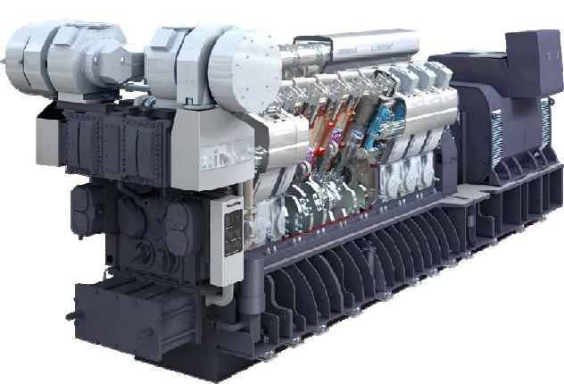
(This picture is for reference only) |
|
|
JICH |
List of standard spare parts |
NO: |
|
Edition/modification’┐Į?/B>2011/A0 |
|
Effective Date :2011,06.07 |
|
1 |
Cylinder head |
Set |
1 |
|
|
2 |
Inlet valve cone |
Set |
1 |
|
|
3 |
Exhaust valve cone |
Set |
2 |
|
|
4 |
Valve guide |
Set |
2 |
|
|
5 |
Pressure spring |
Set |
2 |
|
|
6 |
Pressure spring |
Set |
2 |
|
|
7 |
Inlet valve seat ring |
Set |
1 |
|
|
8 |
Outlet valve seat ring |
Set |
1 |
|
|
9 |
Valve rotating device |
Set |
1 |
|
|
10 |
Axial bearing |
Set |
2 |
|
|
11 |
Valve cone piece |
Set |
1 |
|
|
12 |
Starting valve |
Set |
1 |
|
|
13 |
Nut for main bearing stud |
Set |
1 |
|
|
14 |
Round seal ring |
Set |
1 |
|
|
15 |
Step piston |
Set |
1 |
|
|
16 |
Piston ring |
Set |
1 |
|
|
17 |
Cylinder liner |
Set |
1 |
|
|
18 |
Fire land ring |
Set |
1 |
|
|
19 |
Round seal ring |
Set |
1 |
|
|
20 |
Seal ring |
Set |
1 |
|
|
21 |
Connecting rod |
Set |
1 |
|
|
22 |
Bearing shell |
Set |
1 |
|
|
23 |
Bearing shell |
Set |
1 |
|
|
24 |
Thrust bearing ring |
Set |
1 |
|
|
25 |
Fuel injection pump |
Set |
1 |
|
|
26 |
Injection nozzle |
Set |
2 |
|
|
27 |
Fuel injection valve |
Set |
2 |
|
|
28 |
Fuel injection pipe |
Set |
1 |
|
|
29 |
Main bearing stud |
Set |
1 |
|
|
JICH |
List of standard tools |
NO: |
|
Edition/modification:2011/A0 |
|
Effective Date :2011,06.07 |
|
NO. |
Subject Name |
Part Name |
Q'ty |
Remark |
|
1 |
Cylinder Head and Liner |
Lifting tool for cylinder head |
1 |
|
|
Fitting/Removal device far vale cone/spring |
1 |
|
|
Grinding tool for cylinder head/liner |
1 |
|
|
Extract/suspension device for cylinder liner |
1 |
|
|
Cylinder bore gauge |
1 |
|
|
Removing device for flame ring |
1 |
|
|
Air gun for rotating cap |
1 |
|
|
Feeler gauge for inlet & exhaust valve. |
1 |
|
|
Plier for locking ring |
1 |
|
|
2 |
Piston and Connecting Rod |
Guide for piston |
1 |
|
|
Lifting jig for piston |
1 |
|
|
Holding piece for crank pin bearing |
2 |
|
|
Guide support for connecting rod |
1 |
|
|
Turning bracket for con-rod |
2 |
|
|
Clamping support for con-rod |
2 |
|
|
Plier for piston pin retainer ring |
1 |
|
|
Removal device for valve seat |
1 |
|
|
Lapping device for valve seat |
1 |
|
|
Piston ring opener |
1 |
ŃĆĆ/DIV> |
|
3 |
Crankshaft and Main Bearing |
Lifting device for main fearing |
4 |
|
|
Fitting device for main hearing |
1 |
|
|
Deflection gauge for crankshaft |
1 |
|
|
4 |
Fuel Injection Value |
Test tool for fuel valve nozzle |
1 |
|
|
Lapping device for fuel injection valve bush |
1 |
|
|
Removal tool for atomizer nut |
1 |
|
|
Cleaning tool for fuel valve nozzle |
1 |
|
|
Removal device for fuel injection valve |
1 |
|
|
Long socket far nozzle rout |
1 |
ŃĆĆ/DIV> |
|
Removal device for injection valve bush |
1 |
ŃĆĆ/DIV> |
|
5 |
General Tools |
Max. pressure indicator |
1 |
|
|
Removal device for c.w connection |
1 |
|
|
Tool for air starting v/v |
1 |
|
|
Lapping device for starting v/v |
1 |
|
|
6 |
Hydraulic Tools |
Hydraulic tightening devices M48 |
2 |
|
|
Hydraulic tightening devices M³9 |
1 |
|
|
Hydraulic tightening devices far conrod M³3 |
1 |
|
|
Set of spare parts for hydraulic tools M48 |
1 |
|
|
Set of spare parts for hydraulic tools M³9 |
1 |
|
|
Set of spare parts far hydraulic tools M³3 |
1 |
|
|
Support for main brg M48 |
1 |
|
|
Support for con-rod big end/shaft M³3 |
1 |
|
|
Support for counterweight/side bolt M³9 |
1 |
|
|
Support for cyl.head M48 |
2 |
|
|
Extension screw M48 for cylinder head |
2 |
|
|
Insert screw for con-rod bigend/shaft M³3 |
1 |
|
|
Distribution Pieces 2-POT |
1 |
|
|
Distribution Pieces 4-POT |
1 |
|
|
High pressure hose (L=800) |
2 |
|
|
High pressure hose (L=4000) |
1 |
|
|
Hyd. hand pump& spare kit |
1 |
|
|
Turning pin(╬”10) |
1 |
|
|
7 |
Standard Tool Box |
Spare &Tool box |
2 |
|
About JICH
CNPC JC which locates in Jna economic development zone of china is the only manufacturer that won the National Gold Prize Medal of large power engine and has been awarded China Well-known Trademark of non-road diesel engine. During 10 years great-leap-forward development, Jch has become the main oil drilling power manufacturer in world. and the largest R & D and manufacturing enterprise of non-road medium & high-speed, medium & large-power engines in China. Jch has become a group corporation which has multi-business and inter-province production bases.
The main business of Jch is R & D and manufacturing of internal-combustion engine, compressor, hydrodynamic drive unit, gas power integration unit and engine electrical control device. Selling and service business is included as well. Jch product has been widely used in oil drilling, marine power. power stations, locomotives. construction equipment, military etc. and equipped more than 90% domestic oil drilling teams. Besides, Jch has supplied prime and back - up power for Party and government leading organs. navy submarine bases. Spaceflight bases, mobile communication etc. Jch product covers all domestic oil and gas fields and 32 provinces, autonomous regions, municipalities, Hong Kong, Macao and Taiwan, exports to nearly 60 countries and regions.
|
